ASTM A350 Chemical Compositions Mechanical Properties
ASTM A350 specifies the chemical compositions and mechanical properties of ASTM A350 LF2, LF1, LF3, LF5, LF6, LF9, and LF787.
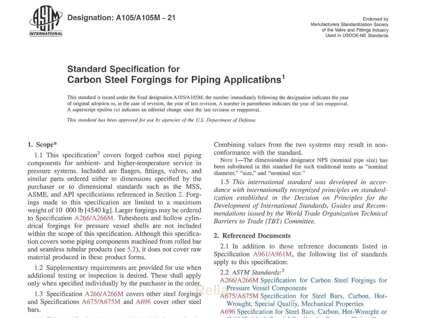
ASTM A350 covers several grades of carbon and low-alloy steel forged or ring-rolled flanges, forged fittings and valves intended primarily for low-temperature service and requiring notch toughness testing.
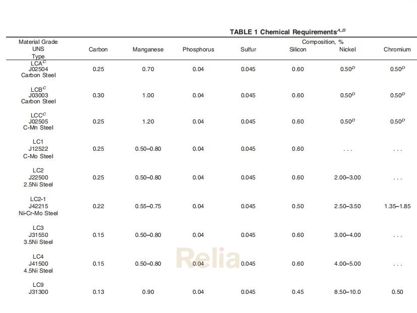
A350 LF2 Casting Equivalent: A352 LCB
A35 LF2 Application: General non-corrosive service,-50ºF (-46ºC) to 800ºF(425ºC)
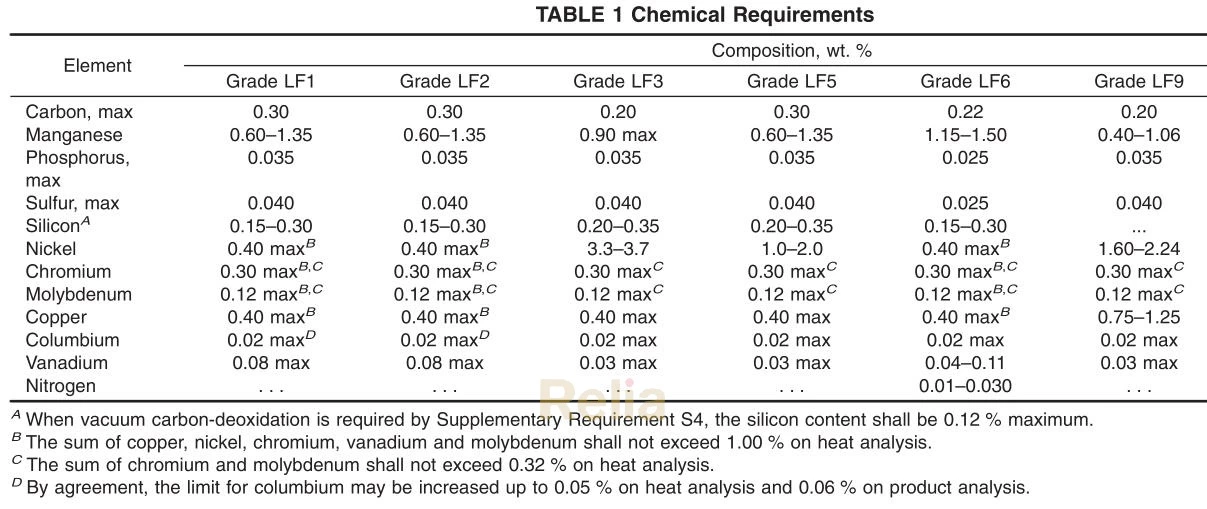
A350 Chemical Compositions
| Element | Composition, wt. % | ||||||
| Grade LF1 | Grade LF2 | Grade LF3 | Grade LF5 | Grade LF6 | Grade LF9 | Grade LF787 | |
| Carbon, max | 0.30 | 0.30 | 0.20 | 0.30 | 0.22 | 0.20 | 0.07 |
| Manganese | 0.60-1.35 | 0.60-1.35 | 0.90 max | 0.60-1.35 | 1.15-1.50 | 0.40-1.06 | 0.40-0.70 |
| Phosphorus,max | 0.035 | 0.035 | 0.035 | 0.035 | 0.025 | 0.035 | 0.025 |
| Sulfur, max | 0.040 | 0.040 | 0.040 | 0.040 | 0.025 | 0.040 | 0.025 |
| SiliconA | 0.15-0.30 | 0.15-0.30 | 0.20-0.35 | 0.20-0.35 | 0.15-0.30 | ... | 0.40 max |
| Nickel | 0.40 maxB | 0.40 maxB | 3.3-3.7 | 1.0-2.0 | 0.40 maxB | 1.60-2.24 | 0.70-1.00 |
| Chromium | 0.30 maxB,C | 0.30 maxB,C | 0.30 maxC | 0.30 maxC | 0.30 maxB,C | 0.30 maxC | 0.60-0.90 |
| Molybdenum | 0.12 maxB,C | 0.12 maxB,C | 0.12 maxC | 0.12 maxC | 0.12 maxB,C | 0.12 maxC | 0.15-0.25 |
| Copper | 0.40 maxB | 0.40 maxB | 0.40 max | 0.40 max | 0.40 maxB | 0.75-1.25 | 1.00-1.30 |
| NiobiumE | 0.02 maxD | 0.02 maxD | 0.02 max | 0.02 max | 0.02 max | 0.02 max | 0.02 min |
| Vanadium | 0.08 max | 0.08 max | 0.03 max | 0.03 max | 0.04-0.11 | 0.03 max | 0.03 max |
| Nitrogen | ... | ... | ... | ... | 0.01-0.030 | ... | ... |
A When vacuum carbon-deoxidation is required by Supplementary Requirement S4, the silicon content shall be 0.12 % maximum.
B The sum of copper, nickel, chromium, vanadium and molybdenum shall not exceed 1.00 % on heat analysis.
C The sum of chromium and molybdenum shall not exceed 0.32 % on heat analysis.
D By agreement, the limit for niobium (columbium) may be increased up to 0.05 % on heat analysis and 0.06 % on product analysis.
E Niobium and columbium are interchangeable names for the same element and both names are acceptable for use in A01.22 specifications.
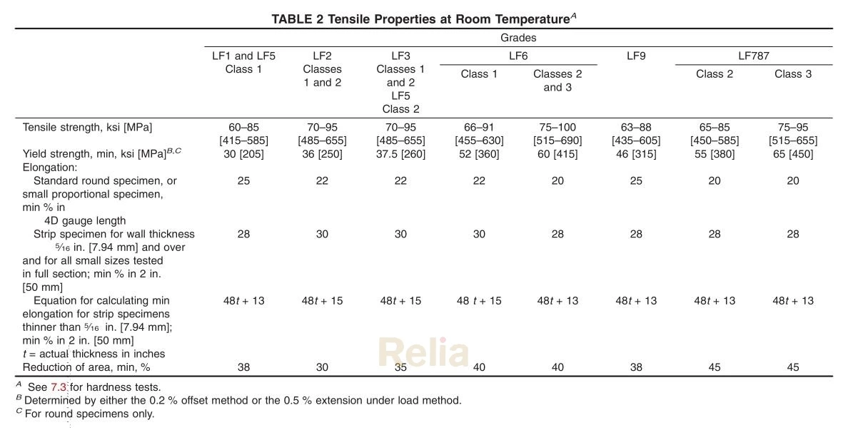
A350 Mechanical Properties
| Grades | ||||||||
| LF1 and LF5 Class 1 | LF2 Classes 1 and 2 |
LF3 Classes 1 and 2 LF5 Class 2 | LF6 | LF9 | LF787 | |||
| Class 1 | Classes 2 and 3 | Class 2 | Class 3 | |||||
| Tensile strength, ksi [MPa] | 60-85 | 70-95 | 70-95 | 66-91 | 75-100 | 63-88 | 65-85 | 75-95 |
| [415-585] | [485-655] | [485-655] | [455-630] | [515-690] | [435-605] | [450-585] | [515-655] | |
| Yield strength, min, ksi [MPa]B,C | 30 [205] | 36 [250] | 37.5 [260] | 52 [360] | 60 [415] | 46 [315] | 55 [380] | 65 [450] |
| Elongation: Standard round specimen, or |
25 | 22 | 22 | 22 | 20 | 25 | 20 | 20 |
| small proportional specimen, min % in 4D gauge length Strip specimen for wall thickness | 28 | 30 | 30 | 30 | 28 | 28 | 28 | 28 |
| 5/16 in. [7.94 mm] and over and for all small sizes tested in full section; min % in 2 in.[50mm] Equation for calculating min |
48t +13 | 48t +15 | 48t +15 | 48t +15 | 48t +13 | 48t +13 | 48t +13 | 48t +13 |
| elongation for strip specimens thinner than %6 in. [7.94 mm]; min % in 2 in. [50 mm] t = actual thickness in inches Reduction of area, min, % | 38 | 30 | 35 | 40 | 40 | 38 | 45 | 45 |
A 7.3 for hardness tests.
B Determined by either the 0.2 % offset method or the 0.5 % extension under load method.
C For round specimens only.
Working Pressure Temperature Rating (ASME B16.34)
A350 Gr. LF2 (1), A350 Gr. LF6 Cl.1 (5), A350 Gr. LF3 (6)
Standard Class
| Temperature, °F |
Working Pressures by Class, psig | ||||||
| 150 | 300 | 600 | 900 | 1500 | 2500 | 4500 | |
| -20 to 100 | 285 | 740 | 1,480 | 2,220 | 3,705 | 6,170 | 11,110 |
| 200 | 260 | 680 | 1,360 | 2,035 | 3,395 | 5,655 | 10,185 |
| 300 | 230 | 655 | 1,310 | 1,965 | 3,270 | 5,450 | 9,815 |
| 400 | 200 | 635 | 1,265 | 1,900 | 3,170 | 5,280 | 9,505 |
| 500 | 170 | 605 | 1,205 | 1,810 | 3,015 | 5,025 | 9,040 |
| 600 | 140 | 570 | 1,135 | 1,705 | 2,840 | 4,730 | 8,515 |
| 650 | 125 | 550 | 1,100 | 1,650 | 2,745 | 4,575 | 8,240 |
| 700 | 110 | 530 | 1,060 | 1,590 | 2,665 | 4,425 | 7,960 |
| 750 | 95 | 505 | 1,015 | 1,520 | 2,535 | 4,230 | 7,610 |
| 800 | 80 | 410 | 825 | 1,235 | 2,055 | 3,430 | 6,170 |
| 850 | 65 | 320 | 640 | 955 | 1,595 | 2,655 | 4,785 |
| 900 | 50 | 230 | 460 | 690 | 1,150 | 1,915 | 3,455 |
| 950 | 35 | 135 | 275 | 410 | 685 | 1,145 | 2,055 |
| 1,000 | 20 | 85 | 170 | 255 | 430 | 715 | 1,285 |
NOTES:
(1) Upon prolonged exposure to temperatures above 800°F, the carbide phase of steel may be converted to graphite. Permissible, but not recommended for prolonged use above 800°F.
(2) Only killed steel shall be used above 850°F.
(3) Not to be used over 700°F.
(4) Not to be used over 850°F.
(5) Not to be used over 500°F.
(6) Not to be used over 650°F.
